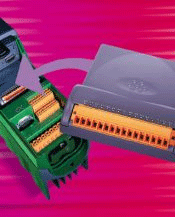
| Key
Features |
|
|
| - |
Full
UD70 functionality
is retained |
| - |
For
use where the reference
signal and motor feedback
signals are both EIA485
quadrature format |
| - |
Can
also be used with
frequency and direction
signals |
| - |
Simulated
encoder output (Quadrature
or frequency and direction
signals) |
| - |
Freeze
input available |
| - |
Encoder
input can be used
as a reference input |
|
|
|
 |
|
|
|
| Specifications |
| |
| Pin Number |
|
Name |
|
Function |
| 40 |
ENCAP |
A or F EIA485
input |
| 41 |
ENCAN |
A\
or F\
EIA485 input |
| 42 |
OV |
|
| 43 |
ENCBP |
B or D EIA485
input |
| 44 |
ENCBN |
B\
or D\
EIA485 input |
| 45 |
OV |
|
| 46 |
ENCZP |
Z EIA485 input |
| 47 |
ENCZN |
Z\
EIA485 input |
| 48 |
OV |
|
| 49 |
FENCAP |
F or A EIA485
output |
| 50 |
FENCAN |
F\
or A\
EIA485 output |
| 51 |
OV |
|
| 52 |
DENCBP |
D or B EIA485
output |
| 53 |
DENCN |
D\
or B\
EIA485 output |
| 54 |
FRZP |
Freeze EIA485
input or Z EIA485 output |
| 55 |
FRZN |
Freeze\
EIA485 input or Z\
EIA485 output |
|
|
| |
| Encoder Inputs
|
| |
| The A, B and Z
inputs may be configured for frequency
and direction or quadrature format.
The position is latched on the
rising edge of Z when the direction
is forward and on the falling
edge when the direction is reversed.
Termination resistors can be selected
by a parameter and do not have
series capacitors. Input filters
and over voltage protection are
fitted to all three inputs. The
inputs comply EIA485. |
| |
| Input loads |
|
1 unit load |
| Termination
resistor |
120 W+/-5% |
| Filter time
constant differential |
350 ns |
| Filter time
constant Common mode |
50 ns |
| max. frequency |
210 kHz Quadrature |
| |
420 kHz F
and D |
|
|
| |
| User Outputs
|
| |
| The F and D outputs,
enable the user to monitor the
Frequency and Direction of the
encoder/Drive signals. The F and
D outputs are derived from either
the main encoder inputs or the
encoder inputs to this module.
The resolution can be reduced
by any power of 2 and the format
of the output can be either frequency
and direction or quadrature. Delay
encoder (main or 2nd) input to
output 1μs. |
|
| |
| User input/output |
|
|
| The signal
can be programmed as a freeze
input or a Z output by setting
the appropriate parameter.
If the Z output is chosen
the output is a buffered
version of the Z input of
the main encoder. If used
as a freeze input when a
positive transition is detected,
the position of both the
main encoder and the 2nd
encoder inputs are stored.
There may be a small delay
in latching the position
but both will be latched
together. Output and Input
modes comply with EIA485.
Termination resistors are
parameter selectable and
do not have series capacitors.
|
|
| |
| Delay Z output
|
|
0ㆍ5 μs |
| Delay from
freeze input to latching
data |
2 μs |
| Time between
latch main encoder and 2nd
encoder |
250 ns |
| Termination
resistance |
120 W+/-5% |
|
|